Soundproof Enclosure for the Monoprice Select Mini 3D Printer
The Monoprice Select Mini printer is an open design, all noise making parts are exposed, and as the stepper motors move the head and the platform, the vibration transfers to the table it is sitting on. There are a few sound proof enclosure designs on the internet, but I have found one that looks cool and easy to assemble. The original design doesn’t use the lid as a platform, but as I found out, the lid on flexible legs and the soft foam insulator under the printer greatly reduces the vibration transferred to the table. My family doesn’t even notice anymore when the printer keeps working overnight on a large model. Without the enclosure, I always had to make sure the printer stopped before bedtime.
The enclosure provides significant noise reduction. I have used an iPhone app to measure the noise from 1 meter distance. The 6dB difference doesn’t look too much, but on the logarithmic scale that means half volume reduction.
- Without the cover: 39 dB
- With cover, door open: 34 dB
- Door closed: 33 dB
I could not measure much difference in noise levels with and without the insulator on the door, but during night printing even a small reduction in noise level counts.
My version of the soundproof enclosure for the Monoprice Select Mini 3D printer is based on the great design announced by Daniel Smith at https://www.thingiverse.com/groups/monoprice-select-mini-owners/topic:16820
The original build instructions are at http://imgur.com/a/1571B
In this post, I will show the modifications I made to the original design. Read the original article for more information.
I re post the bill of materials in case the original article disappears:
- Sound Dampening Insulation – $29.99 https://www.amazon.com/gp/product/B01I4F0J76
- Power Strip with USB Ports – $12.99 https://www.amazon.com/gp/product/B018S7YKSE
- LED Light Strip (I used the warm white color) – $5.99 https://www.amazon.com/gp/product/B016RFHGZS
- Remote Access WiFi Webcam ( I haven’t purchased it yet ) – $29.99 https://www.amazon.com/gp/product/B019MMRV1M
- Blowers with Speed Controller – $30.00 https://www.amazon.com/Coolerguys-Blower-Component-Cooler-Control/dp/B004K3DM2G
- Rubbermaid Storage Container with Window – $18.90 http://www.homedepot.com/p/Rubbermaid-22-0-in-L-x-17-5-in-W-x-15-1-in-H-Large-Access-Organizer-in-Blue-1866947/203837355
- Double sided 3M foam tape
- Elmers Glue
- 8 thin wood screws
- Zip ties
- Clear packing tape
- Magnets to secure the door insulator – $13.50 https://www.amazon.com/gp/product/B01N2RNRJJ
The total cost of my version is about $150, though you can eliminate a few of the line items to bring the cost down if needed. Ended up not buying the web camera, as I can check on the progress anytime by walking to the printer. Maybe later I will buy it to create time lapse videos.
The extra items in the bill of materials above for my design:
- Double sided 3M foam tape to attach the custom legs,
- 8 thin wood screws to secure the blowers.
- Elmers Glue and clear packing tape to secure the dome
- 12 strong magnets to attach the insulator to the door if necessary.
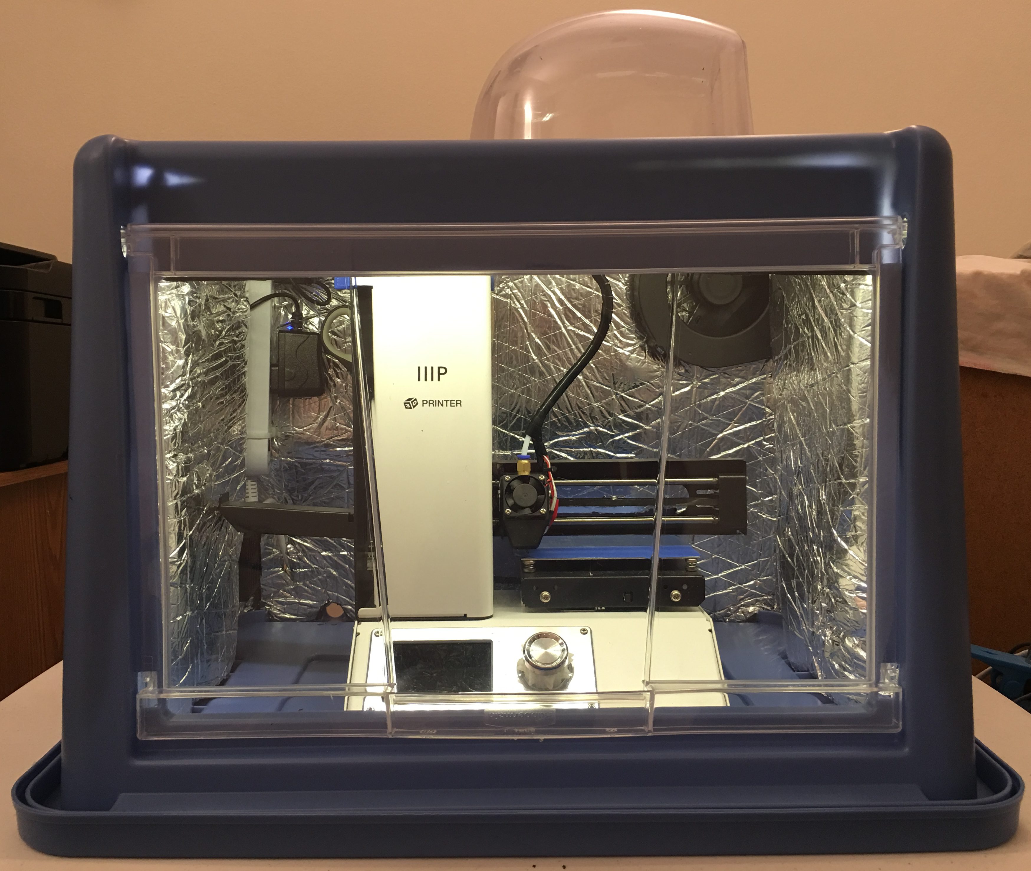
The final product
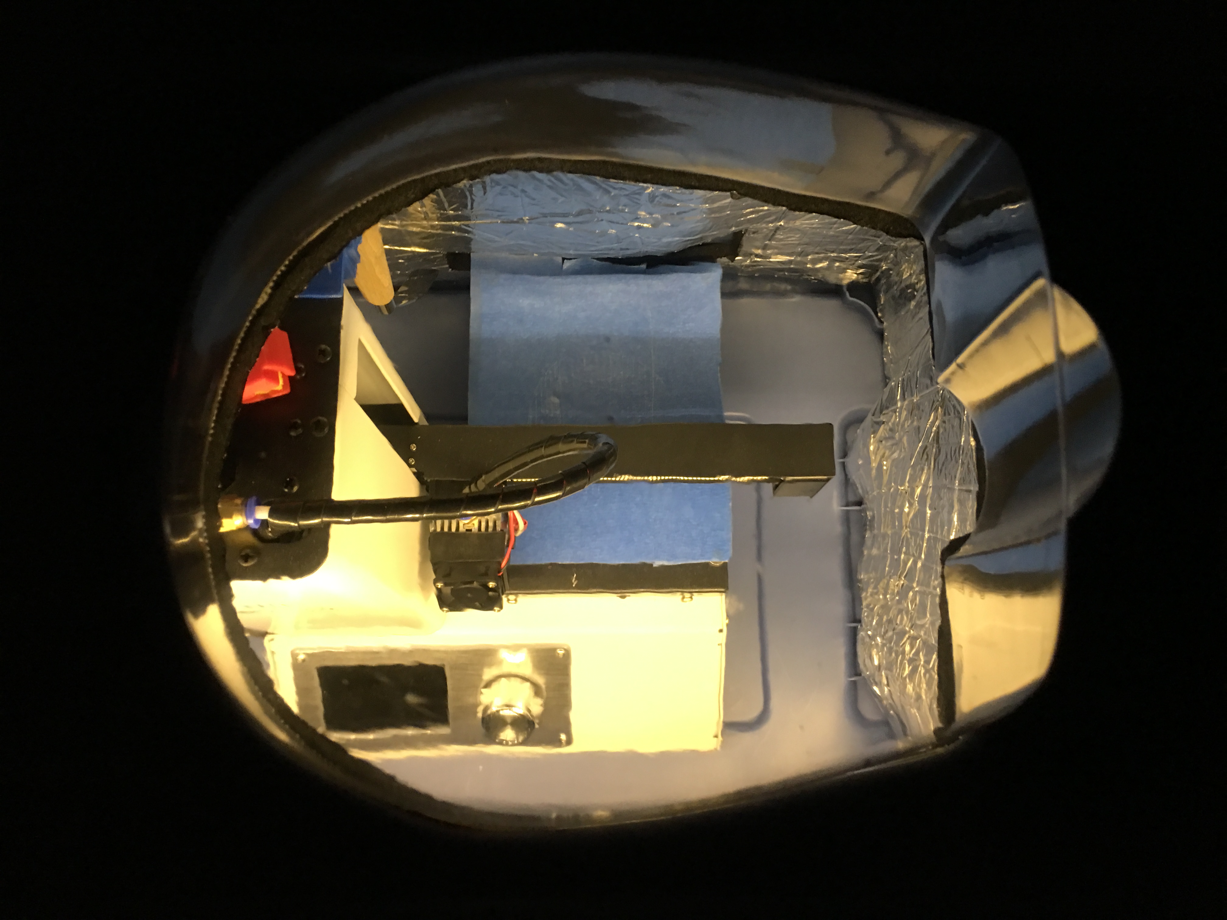
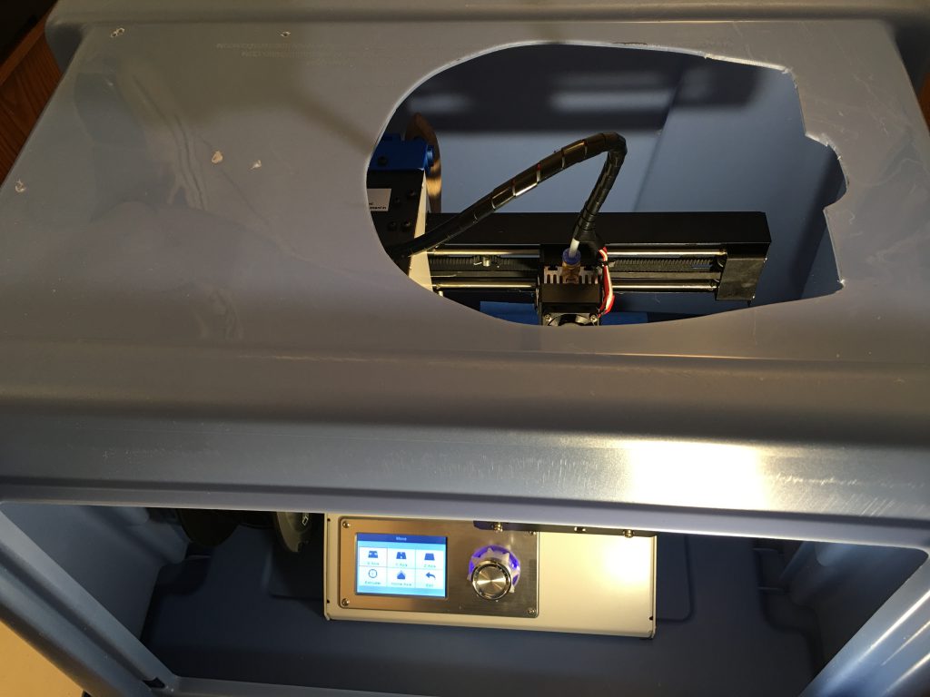
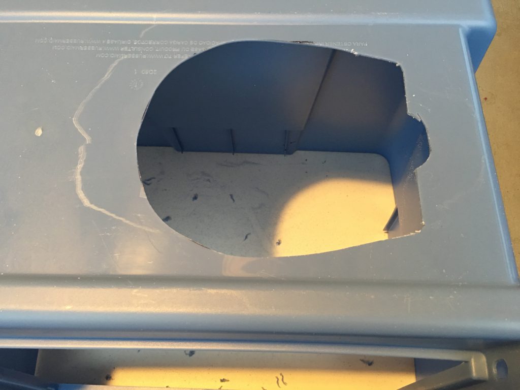
The major differences are the transparent dome on the top and using the lid as the bottom of the box. The dome serves two purposes: Room for the tube at the top of the head, and provides a great view of the 3D object on the platform during the printing process. The lid provides the needed alignment when I put the box above the printer because the build platform almost hits the front and the back of the box.
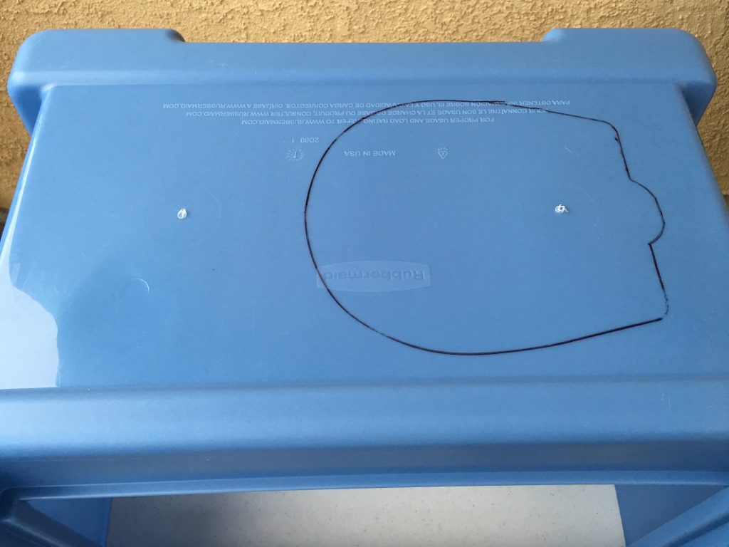
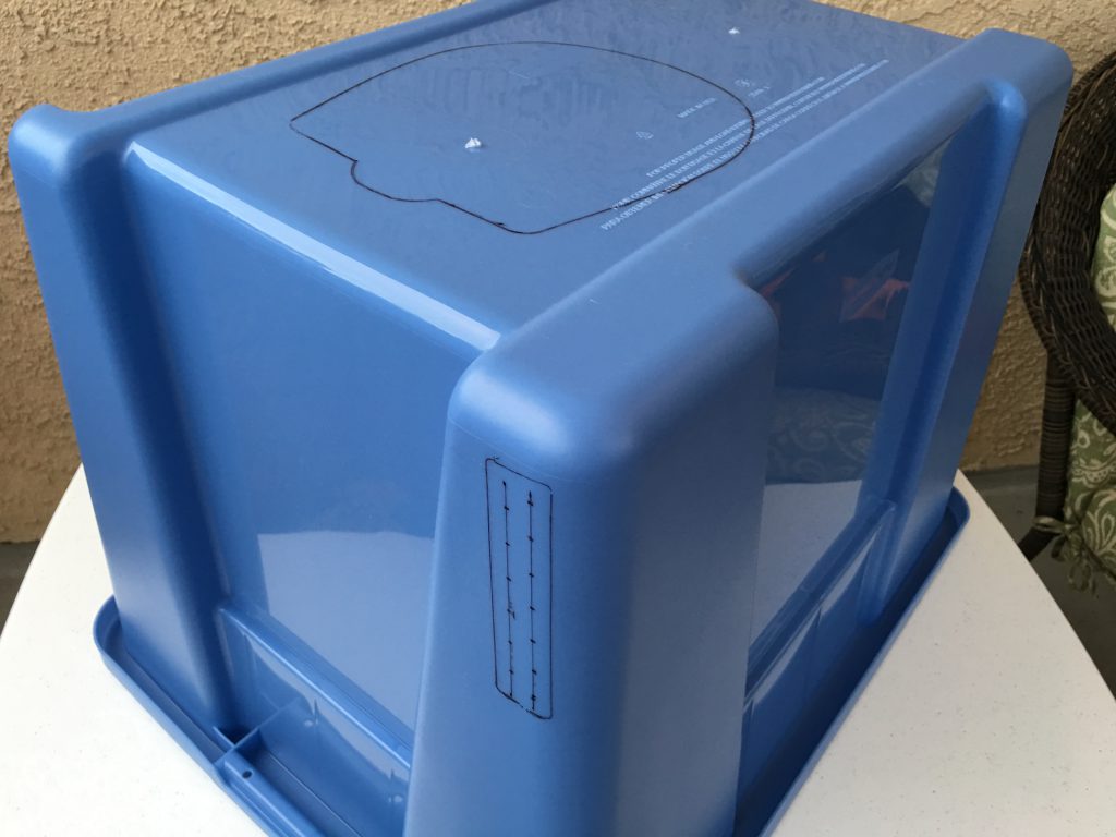
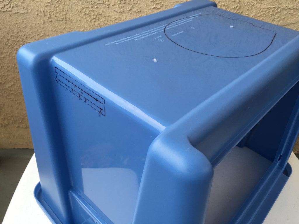
Mark the openings
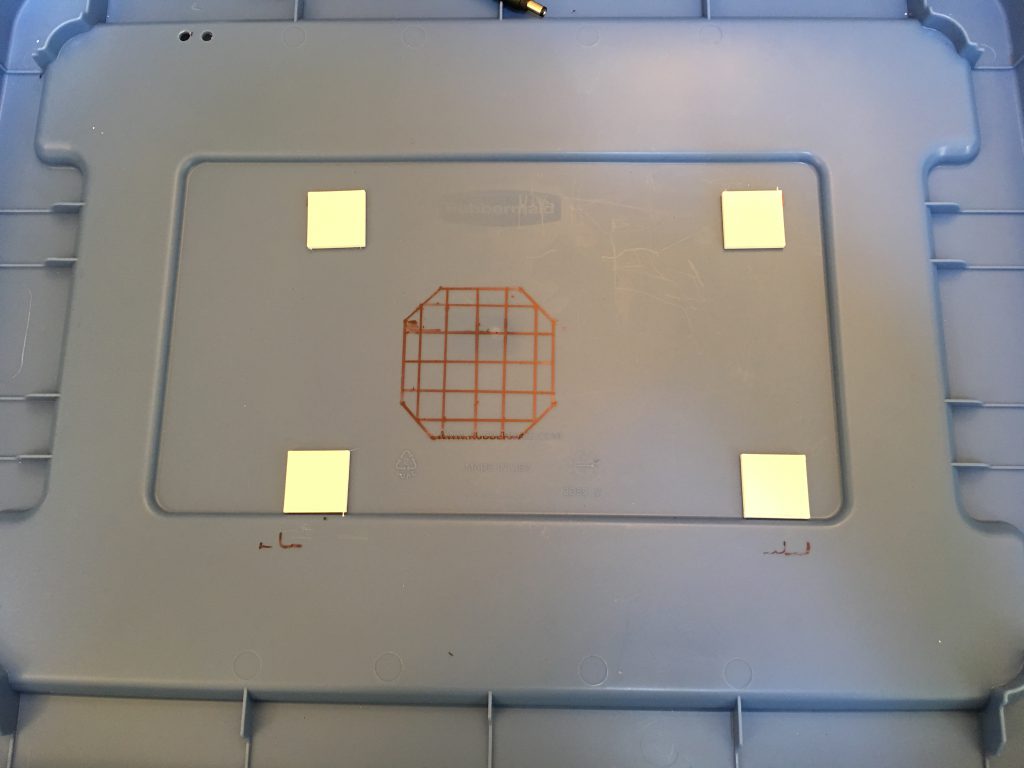
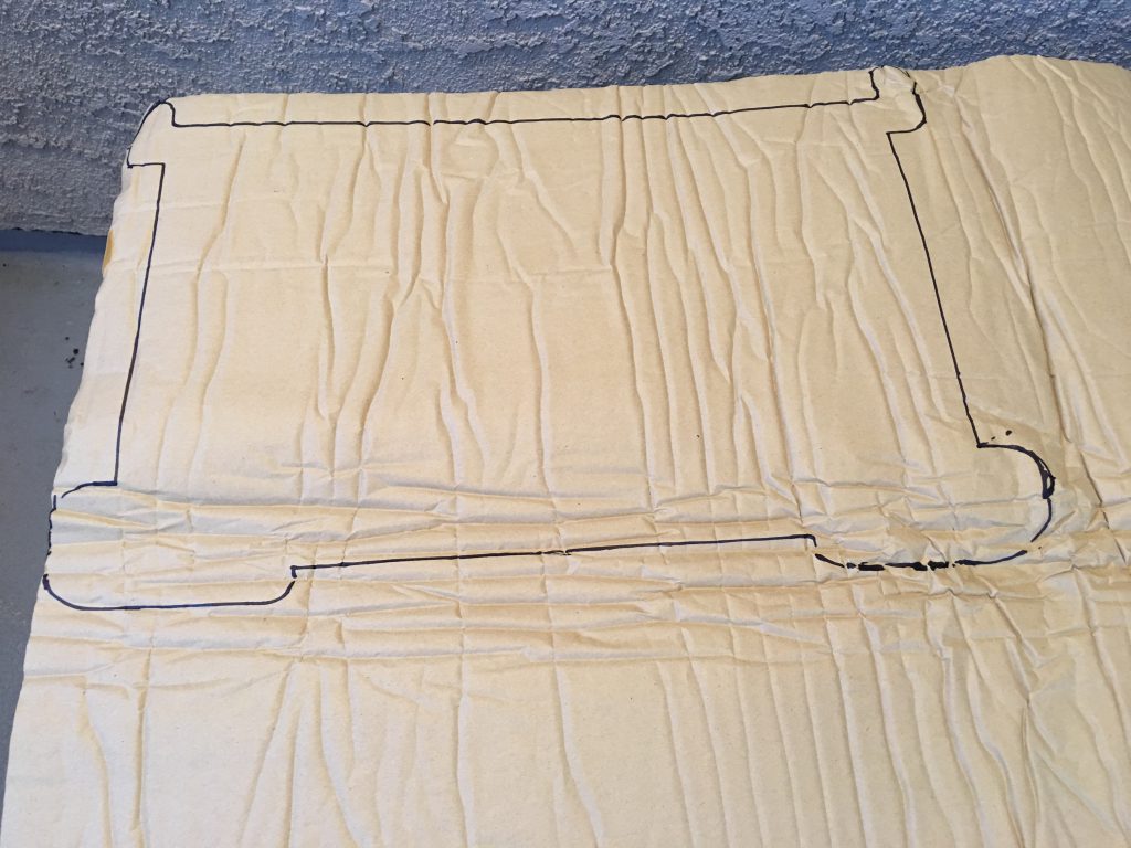
Measure twice, cut once told my father, and he was right. The original author already warned us, because the box sits above the printer upside down, it is very easy to cut the openings on the wrong side of the box. I have started the process with a permanent marker and marked all openings on the box. Before cutting the material, I placed the box above the printer and verified the location of all of them.
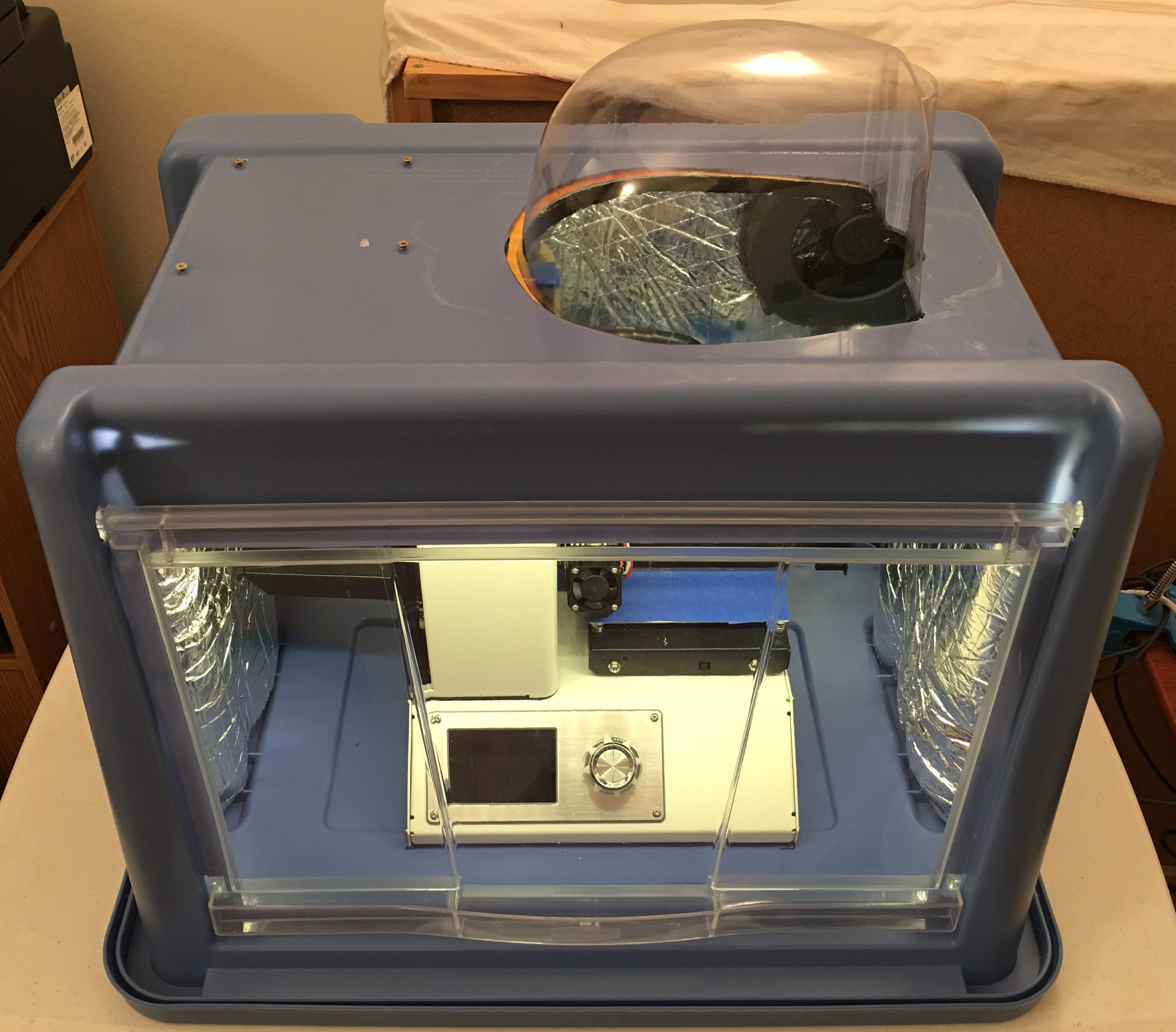
The dome
When the head is at the highest position, the feeding tube needs more room than what the plastic box provides.
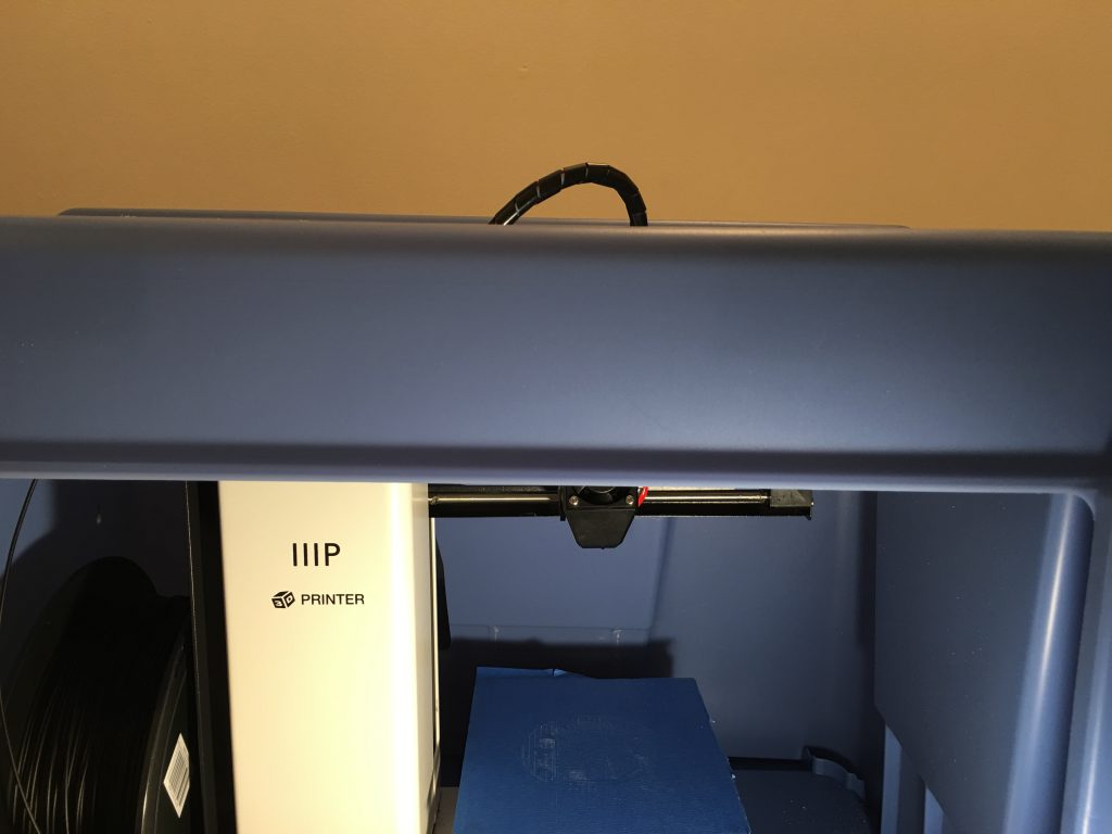
The transparent dome is the packing material of a large headphone. First I cut the opening for the dome with an electric jigsaw.
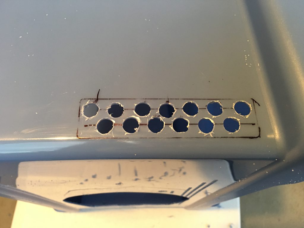
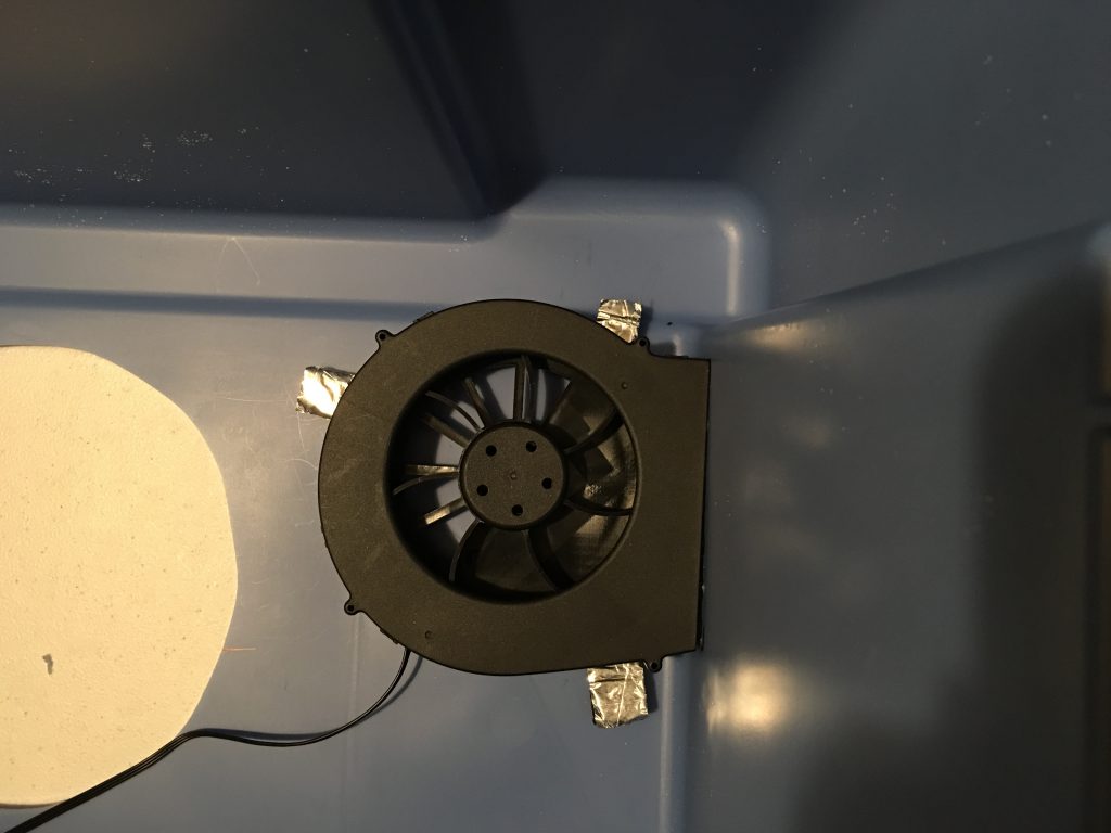
The air outlets
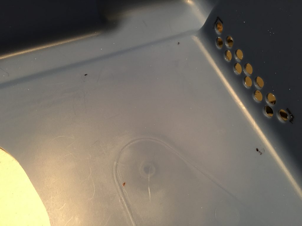
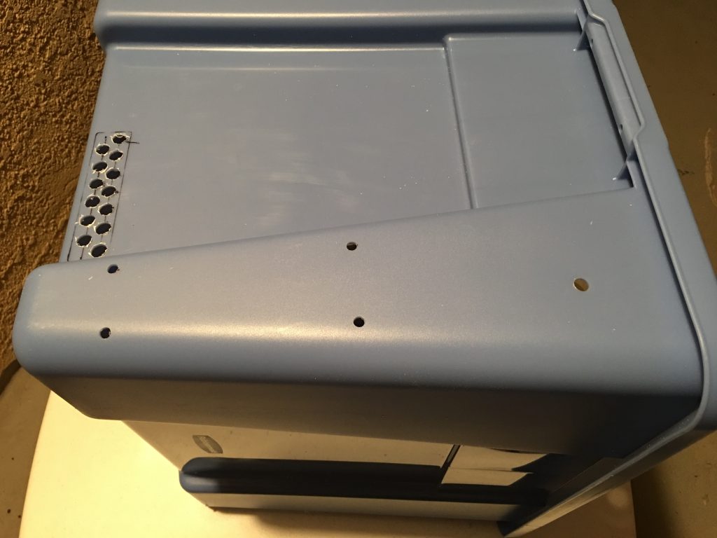
The distance between the hole centers is 15 mm, drill the holes with 8 mm drill bits.
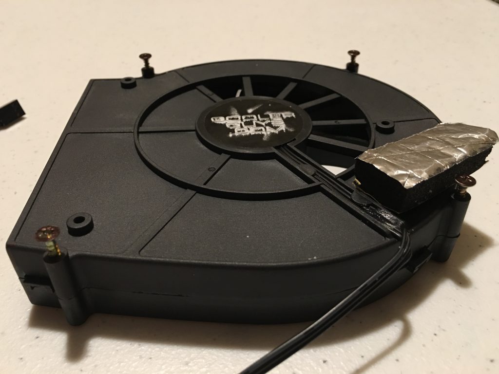
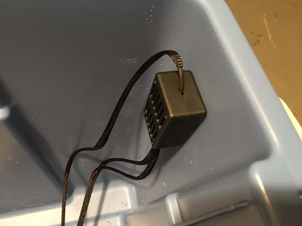
Fan mounting holes
The original plan recommended Super Glue to mount the fans, I wanted a more secure hold, so I used thin wood screws to attach the fans to the box. To mark the location of the holes I inserted the screws into the mounting holes of the fans, painted the heads with the permanent marker and quickly pushed them to the planned location inside the box. After a few tries, I could see the screw locations on the walls. I enlarged the marks with a thick permanent marker and using a flash light copied the locations to the outside surface. To get the correct position I used small strips of the insulating material under the blowers because those will be on the surface of the insulator.
Speed controller
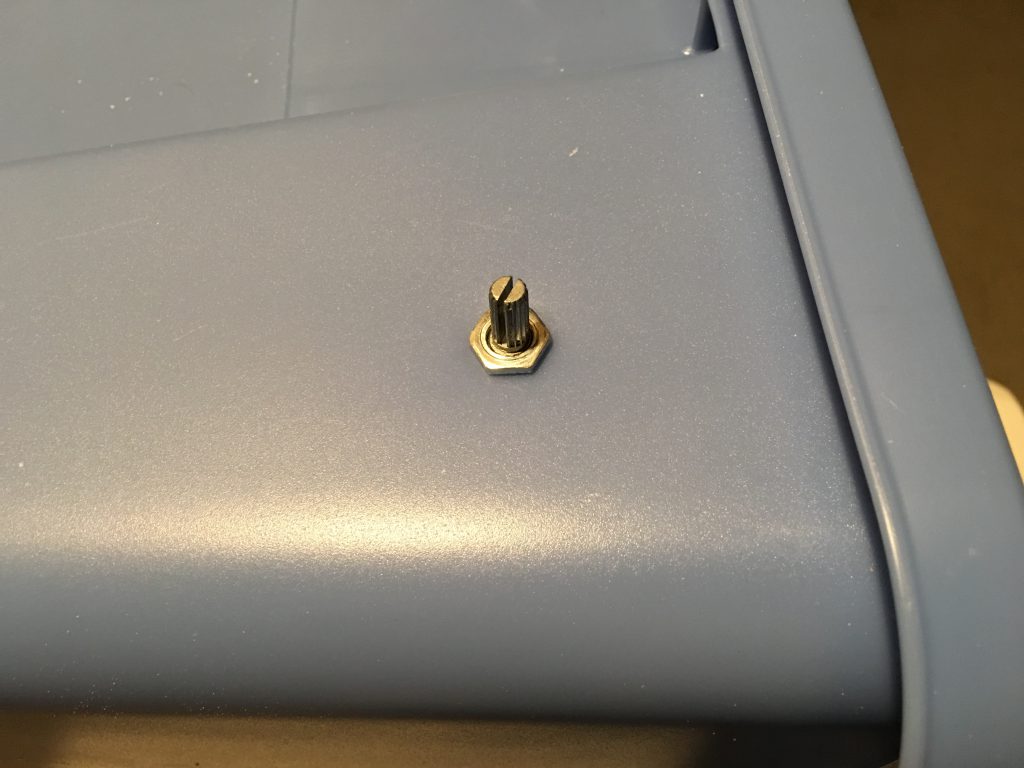
I drilled a hole for the potentiometer of the speed controller and used the nut to secure it below the power strip on the left side.
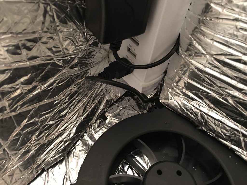
Power strip
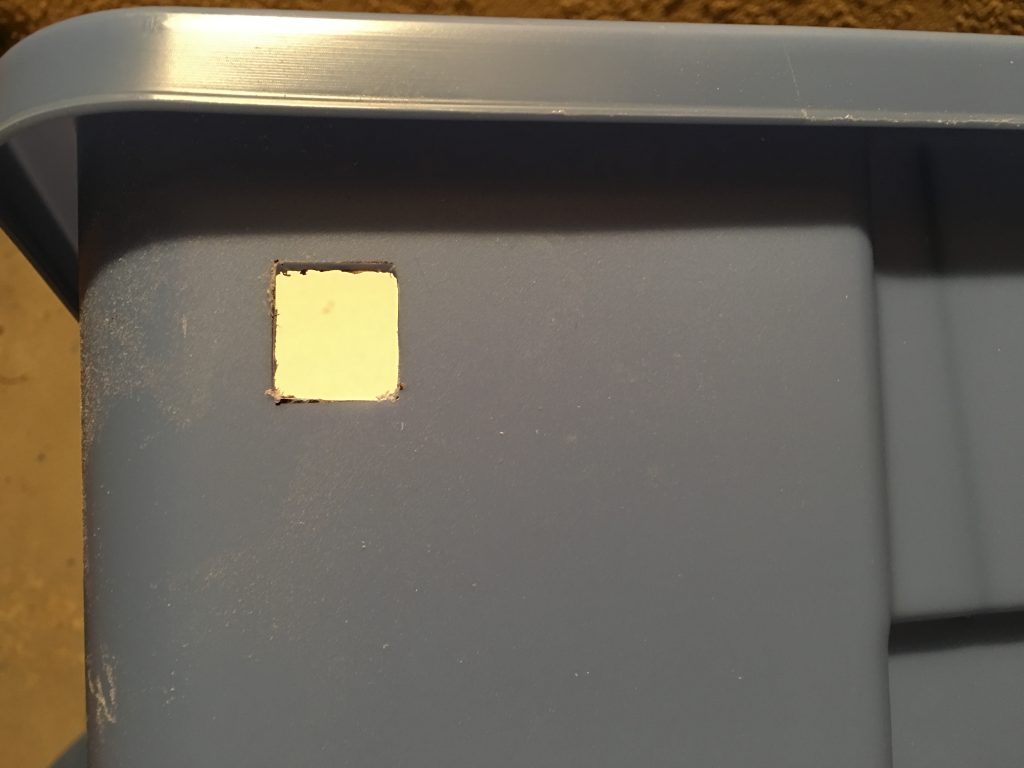
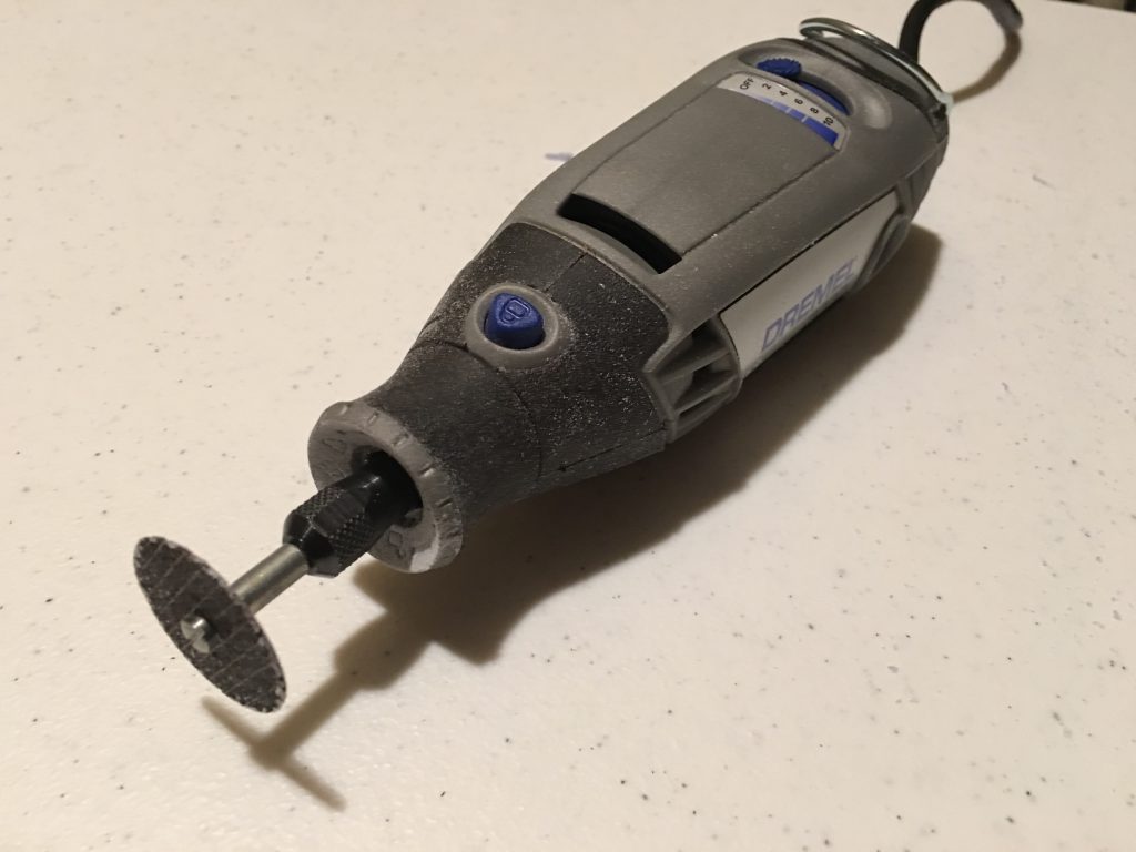
Drilled four holes for the zip ties and cut a square opening with a Dremel tool for the plug.
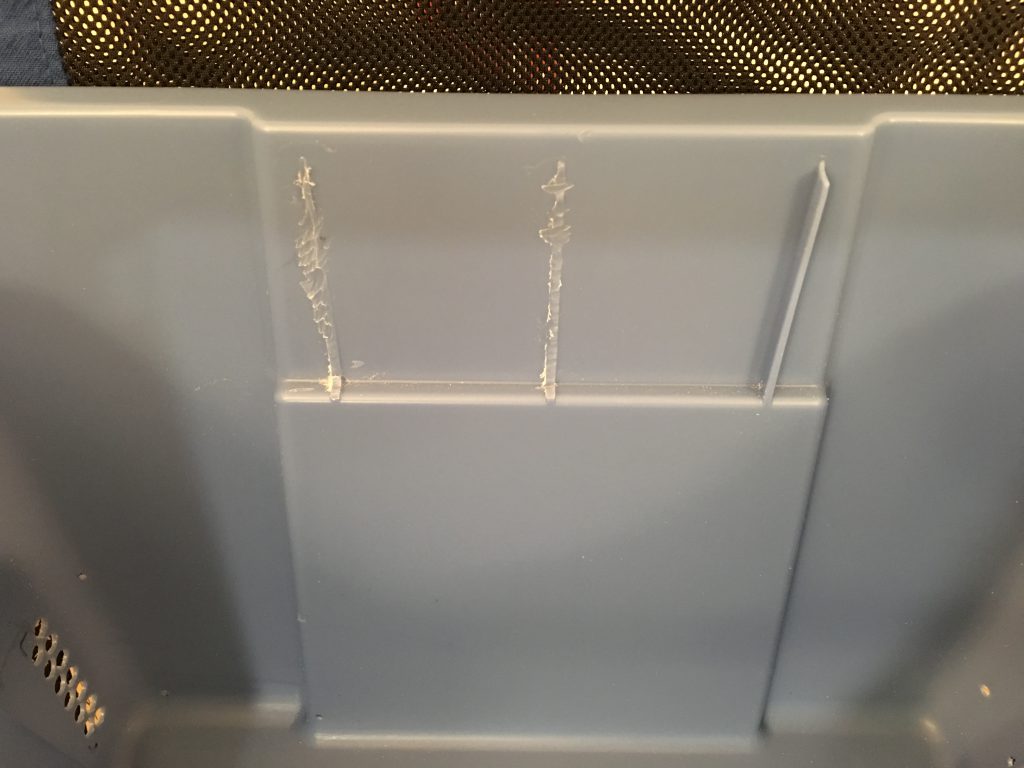
Room for the build platform at the back
THe build platform almost touches the front and the back of the box. To make more room at the back I used the same Dremel tool to remove the ribs from the back of the box.
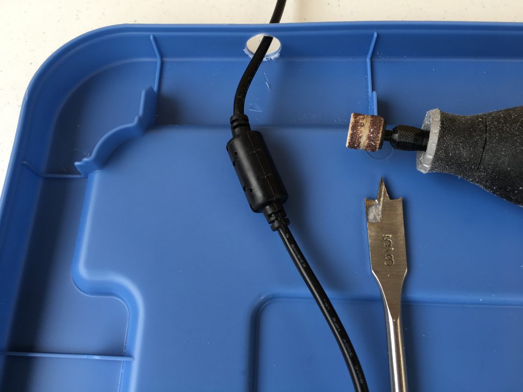
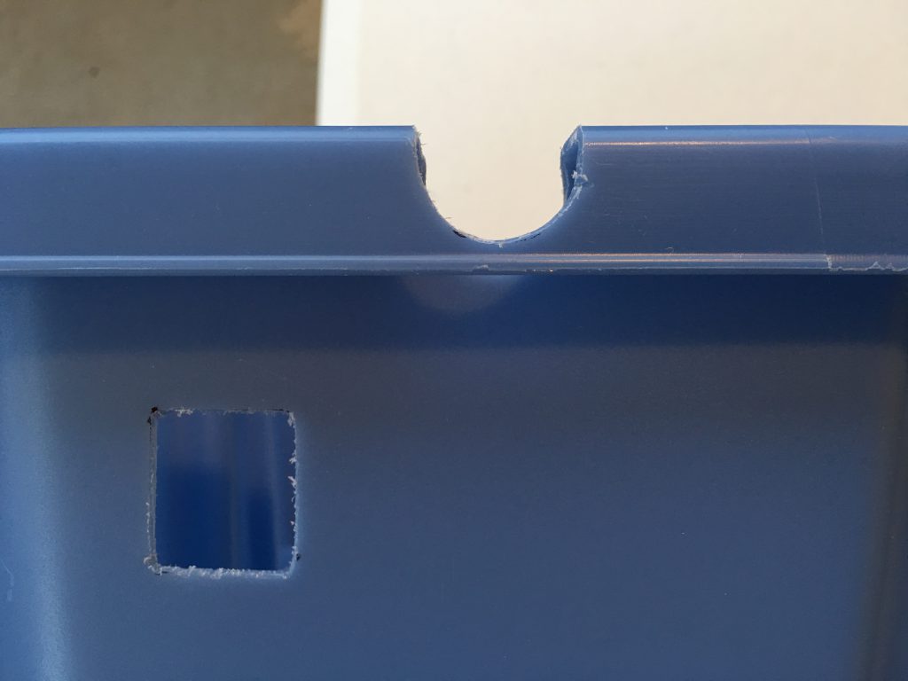
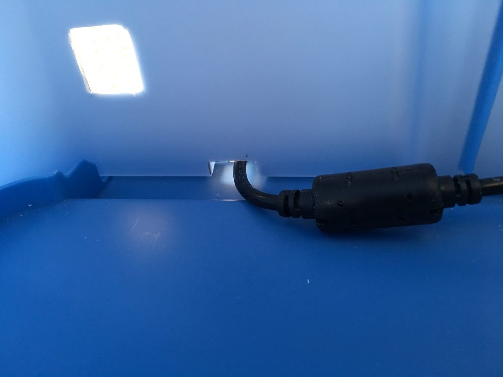
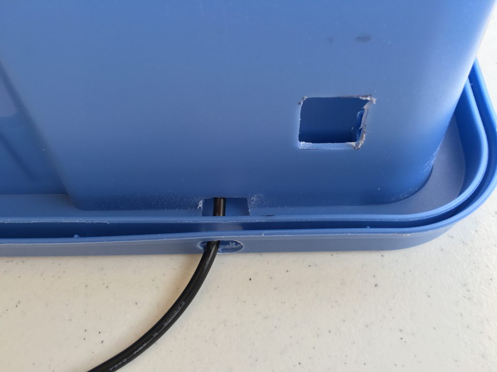
Printer power cable openings
To change the filament, replace the blue painter’s tape on the build platform, or remove a large object, I frequently have to lift the box. To easily position the box over the printer, I use the lid as the base under the printer. To be able to easily remove the box and place it on the floor, the power strip only provides power for the blowers and the LED strip ( I haven’t installed the camera yet ), I left the power supply of the printer outside of the box and plugged it separately into the wall outlet. I used a 5/8″ wood bit and the Dremel tool to enlarge the hole for the barrel plug.
I also drilled two holes for the cable tie to secure the power cord to the lid.
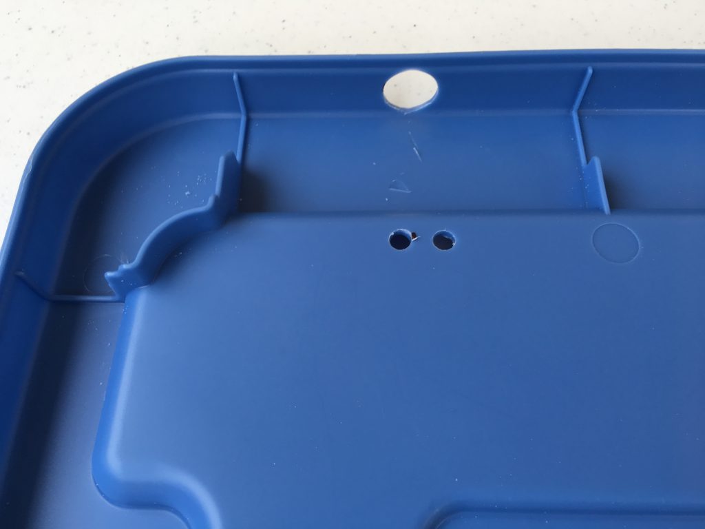
I also had to cut into the edge of the box where the printer power cord enters the box.
Easy lifting
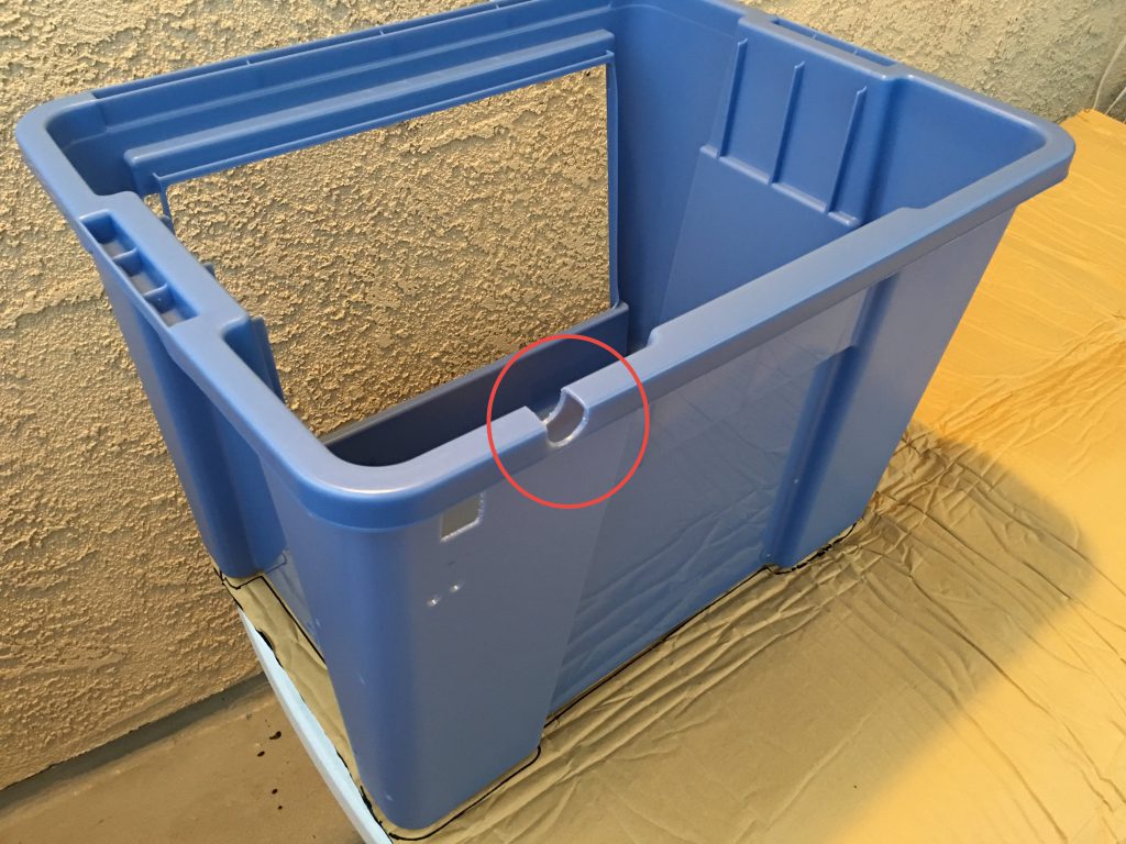
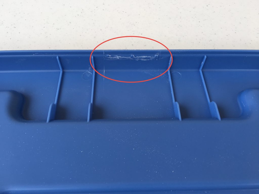
To be able to easily lift the box, I have cut the tabs with the Dremel tool on the sides of the lid where the handles are.
Cool air for the printer
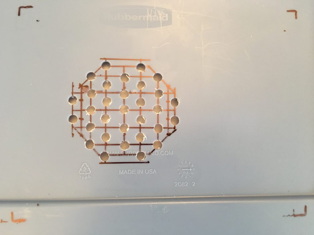
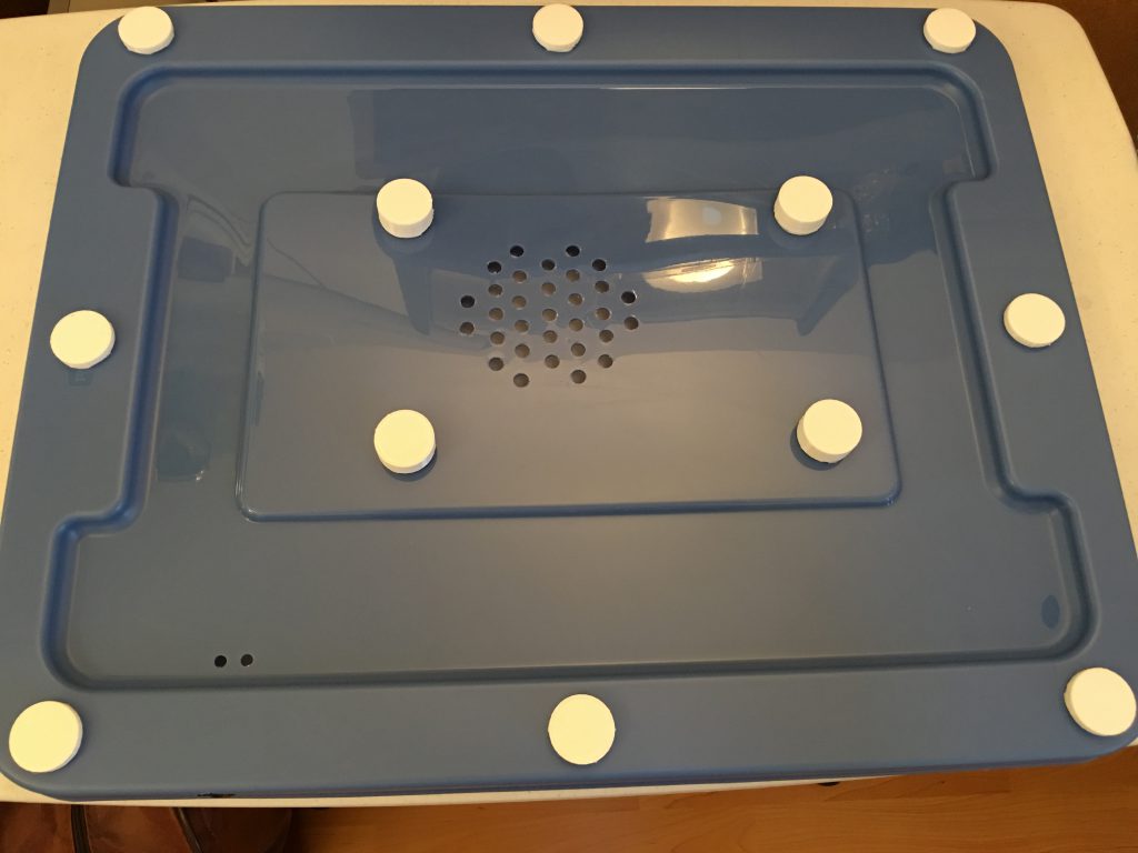
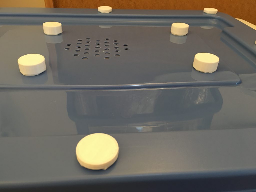
The printer also needs fresh air to cool the control board inside. The Monprice Select Mini has openings at the bottom, so I have cut holes into and elevated the lid with custom legs to provide the air it needs. I used a sheet of paper to copy the exact location of the opening to the lid. The lines are 15 mm apart, and I used an 8 mm bit to drill the holes.
I cut strips of the insulator to lift the printer because I had to pull it forward to provide enough room at the back for the platform. The left side of the printer is much heavier, so it needs more support there.
To provide room for the air flow under the lid, I had to print custom legs for the edge and the center to support the weight of the printer. The diameter of the legs is 30 mm. The height at the edges is 5 mm, under the printer 13 mm. I used the flexible TPU material for better noise reduction, and double sided 3M foam tape to secure them.
Assembly
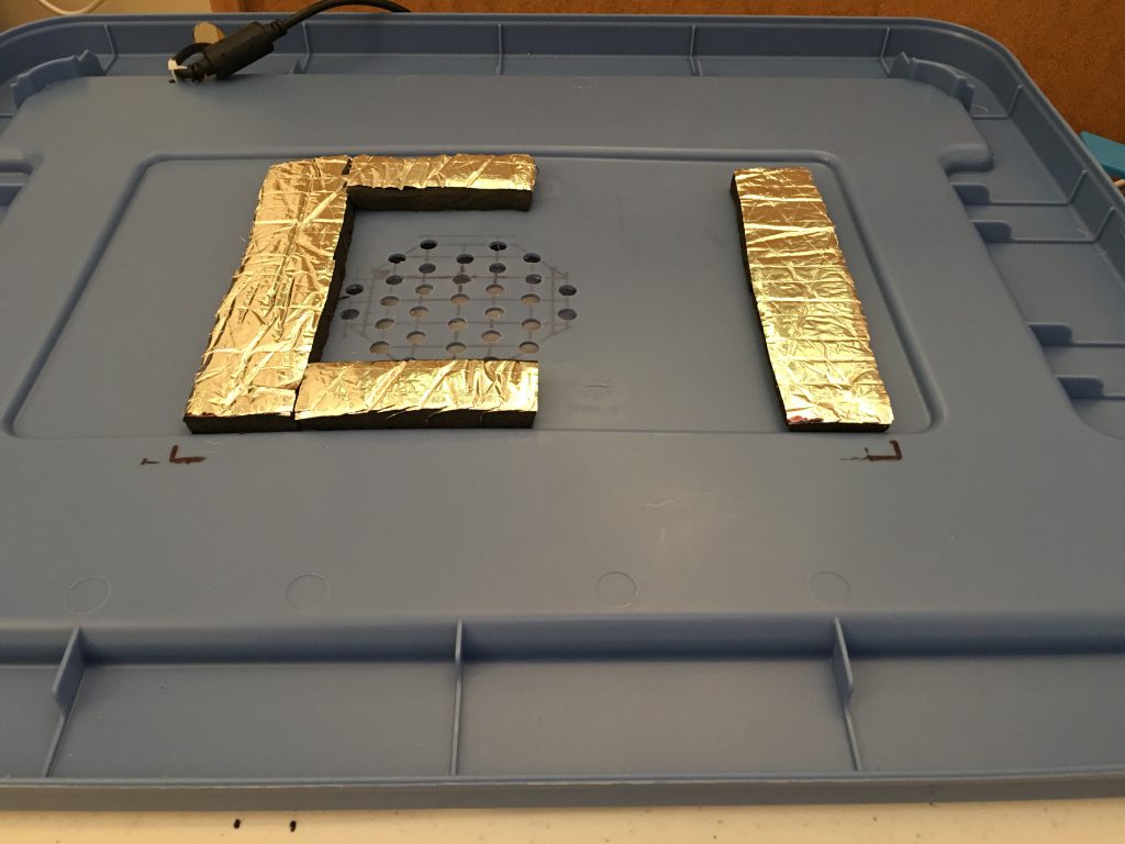
Cut the insulator
I traced the box to cut the insulator. For the back and side walls make the insulator larger because the turns need extra material. You can cut the excess after you have pasted it in place.

Secure the dome
My dome has a 10mm flat edge around, so I used Elmers Glue and transparent packing tape to secure the dome from the inside of the box. The insulator provides the additional support. I put the blower wires under the insulator of the back wall. Cut an opening in the insulator for the speed controller, do not hide it, because it needs air for cooling. Cut into the insulator for the output of the blowers.
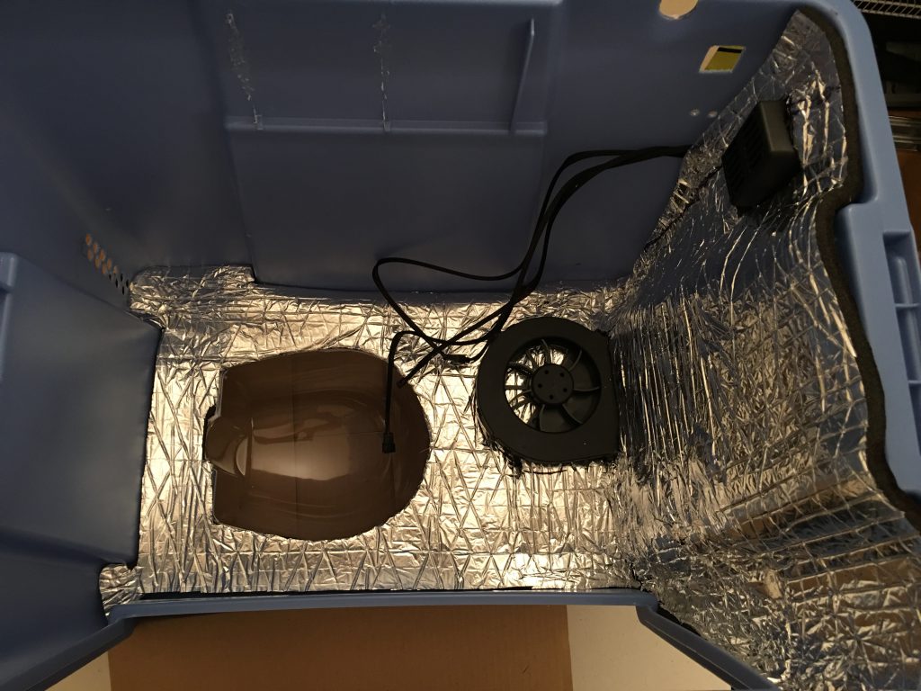
Cut into the insulator where the build platform needs extra room.
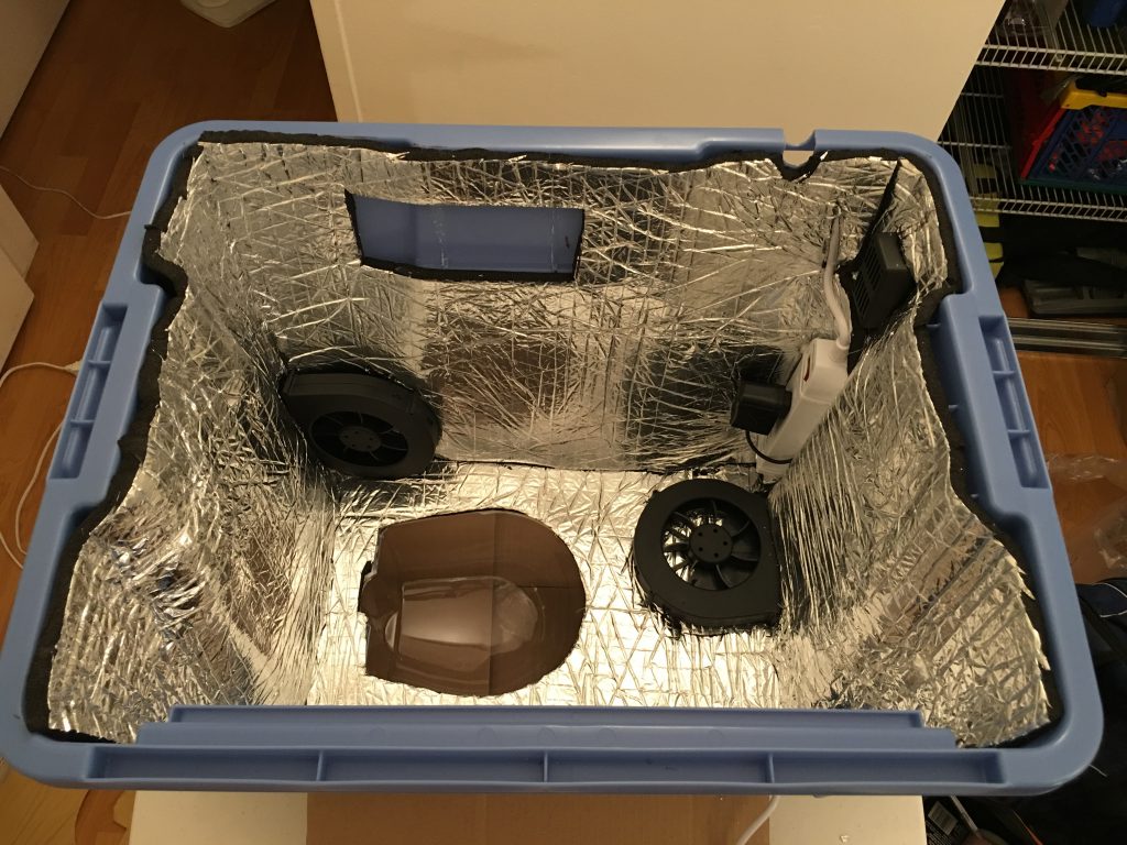
LED lights
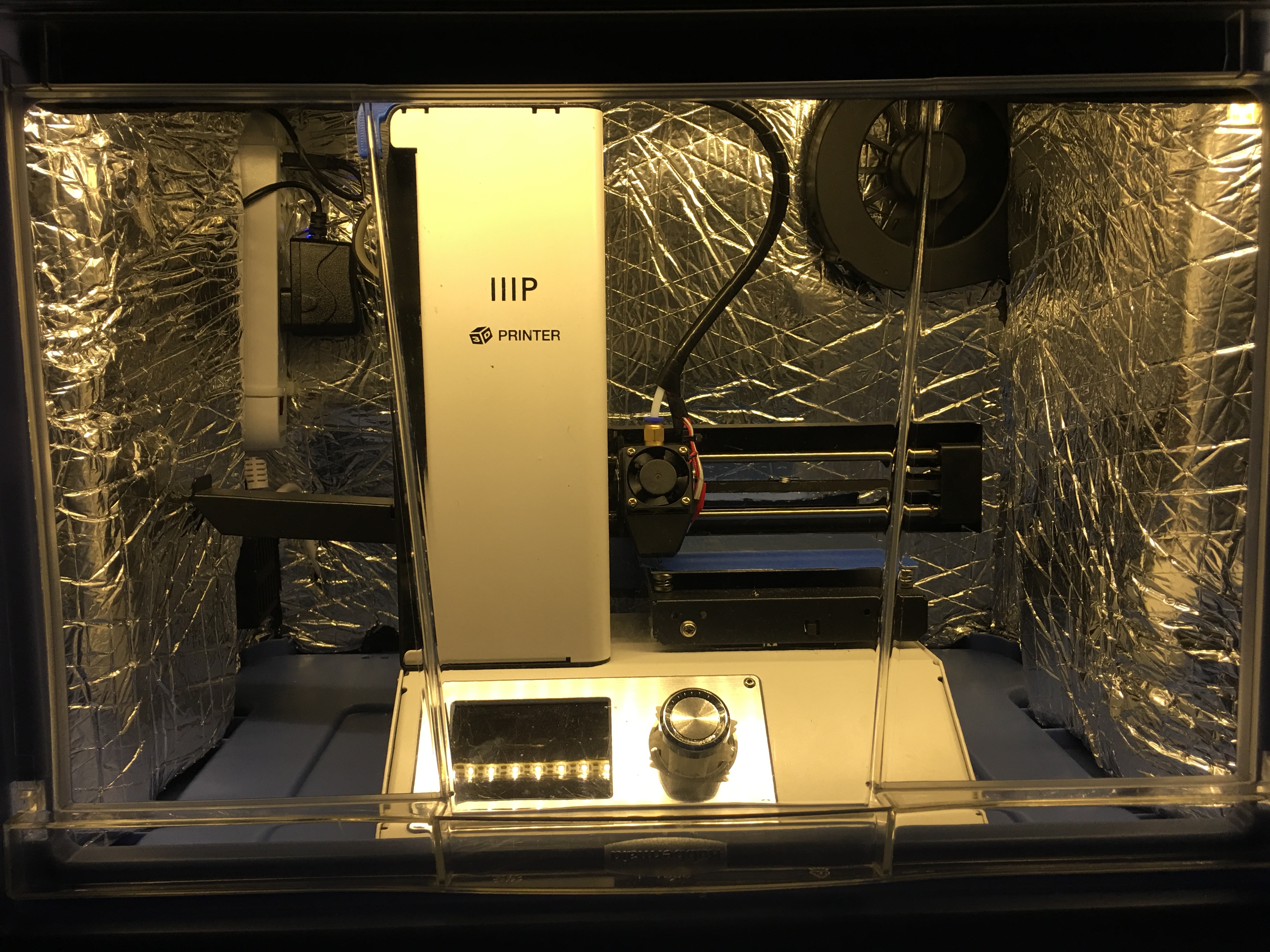
Install the LED strip above the door and hide the wire under the insulator. Use the USB outlets of the power strip to power it.
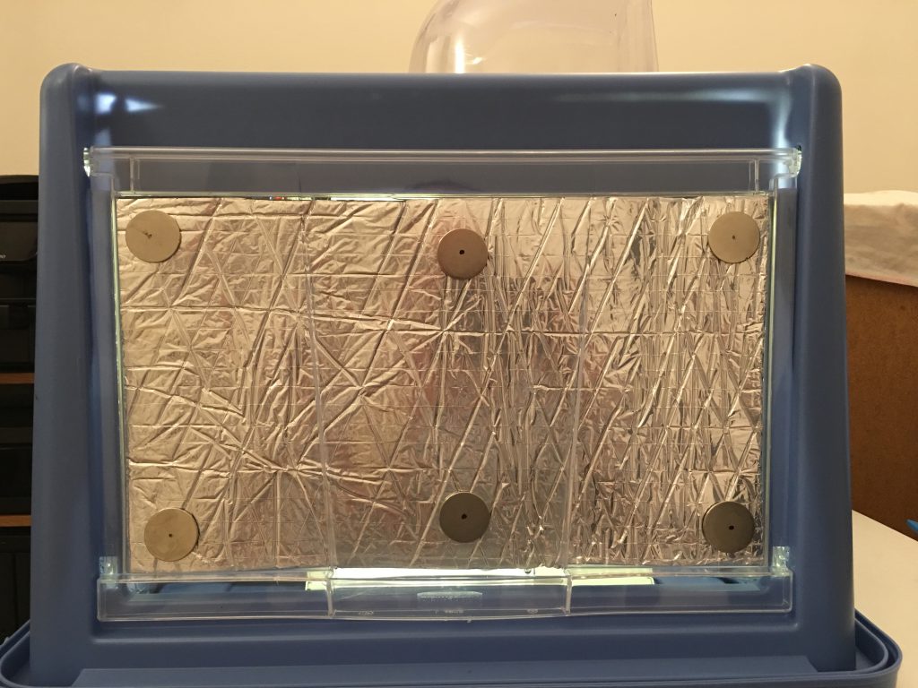
Door insulation
I left the protecting paper on the insulator for the door. I use 12 strong magnets to be able to attach and easily remove the insulator from the door. I hold a magnet on the inside surface of the insulator, and another one on the outside of the door. I could not detect significant noise level differences with our without the door insulator, but during night printing every decibel counts.