Prevent the auto-termination of stranded instances in RighScale

When you launch an instance with RightScale Self Service, and the Chef cookbook execution fails, the instance goes into “stranded” mode. By default RightScale Self Service terminates the stranded instances, so there is no way to remote into them and read log files to find the cause of the problem.

To keep stranded instances running in RightScale

  1. Find the booting instance in Cloud Management and click the instance name,
  2. Click the lock icon on the top of the screen

RightScale Self Service cannot terminate locked instances. To terminate the instance after the troubleshooting process, unlock the instance and terminate the instance by hand.

Getting started with InSpec

InSpec is an open-source testing framework to verify your infrastructure satisfies the design requirements.

In this article, we will learn to install and use InSpec with Chef.

Install InSpec

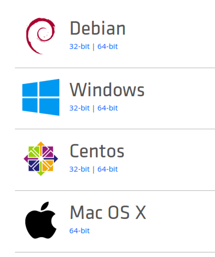
  1. Navigate to https://downloads.chef.io/inspec, and download the installer for the operating system of your workstation,
  2. Execute the downloaded installer.

Allow InSpec to verify Red Hat Enterprise Linux instances

InSpec needs “sudo” access to execute the tests, but Red Hat Enterprise Linux prevents that access. Execute the following code on every instance when it runs in Test Kitchen:

if (node.chef_environment == "_default")
  # Running in Test Kitchen

  # Ensure sudo is installed
  package 'Install sudo' do
    package_name 'sudo'
    action :install
  end

  file '/etc/sudoers' do
    mode 0440
    owner 'root'
    group 'root'
    action :create
  end

  delete_lines 'remove hash-comments from /some/file' do
    path '/etc/sudoers'
    pattern '^.*requiretty'
  end

end


Start to use InSpec

To use InSpec as the default integration testing tool in Chef Test Kitchen

  1. Open the .kitchen.yml file of the cookbook,
  2. Delete the following lines from the platform section if exist:
    busser:
      sudo: true
  3. Add the following lines to the file between provisioner: and platforms:
    verifier:
      name: inspec
  4. Place the test files into the default location of the InSpec integration test. The “verify” command executes all files in the directory.
    test
    |--smoke
       |--default
          |--MY_RECIPE_NAME1_test.rb
          |--MY_RECIPE_NAME2_test.rb
    
  5. To execute the test file with the verify command, add these lines to every suite. This will execute all test files in the default folder.
        verifier:
          inspec_tests:
            - test/smoke/default
  6. To execute only one test file, specify the file name:
        verifier:
          inspec_tests:
            - test/smoke/default/MY_RECIPE_test.rb
  7. To execute the test file of another suite, use relative path, you can use tests from other cookbooks (../ANOTHER_COOKBOOK/test/recipes/ANOTHER_SUITE_NAME).
        verifier:
          inspec_tests:
            - ../ANOTHER_COOKBOOK/test/smoke/default
  8. Create an integration test for your recipe. Create a new file in the test/recipes/THE_SUITE_NAME folder. The name does not matter, if you are planning to create only one test file for the suite, name the file after the suite: default_test.rb,
  9. The following is a simple example of an InSpec integration test:
    # # encoding: utf-8
    
    # Inspec test for recipe my_cookbook::default
    
    # The Inspec reference, with examples and extensive documentation, can be
    # found at https://docs.chef.io/inspec_reference.html
    
    unless os.windows?
     describe user('root') do
     it { should exist }
     skip 'This is an example test, replace with your own test.'
     end
    end
    
    describe port(80) do
     it { should_not be_listening }
     skip 'This is an example test, replace with your own test.'
    end

As you can see, the syntax of InSpec is (intentionally) very similar to ServerSpec, that it replaces. It is very easy to convert existing ServerSpec integration tests to InSpec compliance tests.

Differences between ServerSpec and InSpec

ServerSpec “process”

Does not work on a Windows host.

On Linux the syntax changed from

 describe process('PROCESS_NAME') do
   it { should be_running }
 end

to

describe processes('PROCESS_NAME') do
  its('states') { should eq ['R<'] }
end

registry_key

The :dword comparison uses the decimal value with no quotes instead of the hex value with quotes

changed from

describe registry_key('HKEY_LOCAL_MACHINE\SOFTWARE\Microsoft\NET Framework Setup\NDP\v4\Full') do
  it { should have_property_value('Release', :dword, '70805') } # 460805 decimal
end

to

describe registry_key('HKEY_LOCAL_MACHINE\SOFTWARE\Microsoft\NET Framework Setup\NDP\v4\Full') do
  it { should have_property_value('Release', :dword, 460805) } # For dword use the decimal value, no quotes
end


For more information

For more information on the Kitchen InSpec verifier visit https://github.com/chef/kitchen-inspec

Import STL mesh files into Autodesk Inventor

Import and export STL mesh files

To enable Autodesk Inventor to open and save .stl files add the STL Import and STL Export add-ins to Adobe Inventor. .stl files are used to transfer 3D print designs between computers. You can download most of them for free from the Internet.

  1. In the Tools menu open the Add-in Manager
  2. On the Translators tab select the STL Import and STL Export translators.

To be able to edit the STL mesh files

install the Mesh Enabler add-in

Download the Autodesk Inventor Mesh Enabler

  1. Navigate to the Autodesk app store at https://apps.autodesk.com/en
  2. Sign in with your Autodesk account
  3. Search for Mesh Enabler
  4. Click the Download button

Install the Autodesk Inventor Mesh Enabler

  1. Double click the downloaded AutodeskMeshEnabler.msi file and complete the installation
  2. Start Autodesk Inventor
  3. In the Tools menu select the Add-in Manager
  4. On the Applications tab select Autodesk Mesh Enabler
  5. Select the Load Automatically checkbox
  6. Click OK

To convert an STL mesh file to a solid model

  1. Start Autodesk Inventor
  2. Open the STL mesh file
  3. In the browser right-click the MeshFeature1 element and select Convert to Base Feature
  4. In the dialog box select the output you need and click OK.

    1. Solid/Surfaces: Converts the selected mesh features to multi-solids or individual surfaces. To create solids, the mesh features must form closed meshes.
    2. Composite: Converts the selected mesh features to a single composite feature.
    3. Delete Original: Deletes the selected mesh features after conversion.

Set the default project location

Inventor saves the new projects in your document folder. To set a different default location

  1. In the Tools menu select Application Options
  2. On the File tab click the yellow folder icon next to Project folder and set the desired location.

To save the solid model as an STL 3D mesh

  1. Open the Inventor Parts (.ipt) or Inventor Assembly (.iam) file in Autodesk Inventor,
  2. Click the Inventor icon in the upper left corner,
  3. Click the small arrow next to Save As,
  4. In the submenu select Save Copy As,
  5. In the Save as type dropdown select STL Files,
  6. Enter a name for the file and click Options…,
  7. Select Source Units to make sure the size of the mesh is identical to the objects in the Inventor document,
  8. Click OK to close the Options window,
  9. Click Save to write the file to the disk.

Recommended 3D Printer settings

There are many 3D printers, filaments, and project types out there, so the variations of 3D printer settings are almost limitless. This page contains recommended settings for the most common 3D printing jobs, printers, and materials.

Printing materials

Filament material Shore A hardness Shrinkage Platform adhesion Advantages
PLA Blue painters tape  Less warping, No heating bed required, Eco-friendly, Odorless
ABS Kapton tape or Hairspray  Prints at higher temperature, Durable, Requires less manual finishing, Process in acetone for polished finish, UV resistant
PETG Blue painters tape or Kapton tape or Glass bed  Hydrophobic (does not absorb moisture), Odorless, Environmentally safe, Easy adhesion to a number of surfaces, No heating bed required
PPLA Blue painters tape or Kapton tape  Less warping than PLA, Eco-friendly, No heating bed required, Odorless
TPE 85A (very soft)  1.2 – 3.0% Blue painters tape or Kapton tape  Flexible, Easy to clean, Will adhere to most surfaces
TPU 94A (pretty soft)  0.8 – 1.8% Blue painters tape or Kapton tape  Flexible, Easy to clean, Will adhere to most surfaces
Filament material Strength Ease of use Odorless Felxibility Chemical resistance Abrasion resistance
PLA  [][][][  [][][][]  [][][][][]  [][][
ABS  [][][][]  [][][][  [] [  [][]
PETG  [][][][][  [][][][][  [][]  [][
PPLA  [][][][  [][][][][  [][][][][]  [][][
TPE  [][][]  [][][]  [][][][][]  [][][][][]  [][][]  [][]
TPU  [][][]  [][][][]  [][][][][]  [][][][][  [][][][]  [][][][][]

Printer settings for filament type

Filament material Nozzle temperature range (recommended) Build platform temperature range (recommended) Print speed
3D Solutech PLA
1.75 mm  and 3 mm
190-220 °C
(205 °C)
0-60 °C
(50 °C)
50 mm/s
Hatchbox PLA
1.75 mm  and 3 mm
180-210 °C
(195 °C)
0-60 °C
(50 °C)
50 mm/s
Hatchbox ABS
1.75 mm  and 3 mm
210-240 °C
(225 °C)
55- 85 °C 50 mm/s
Hatchbox PETG
1.75 mm  and 3 mm
230-260 °C 55- 85 °C 50 mm/s
Hatchbox PPLA
1.75 mm  and 3 mm
180-220 °C 55- 85 °C 50 mm/s
Hatchbox TPU
1.75 mm  and 3 mm
180-210 °C 55- 85 °C 30 mm/s

Printer settings for job type

For the best look, select the closest recommended layer height for your printer. See Layer Height below for the explanation.

Job type Layer height (mm) Fill density (%) Print speed (mm/s) Minimal layer cool time (sec)
Decorative 0.1 15 50 3
Light duty, mainly straight pull (casing, rotor blades)  0.1 30 50 3
Light duty (fast printing of parts with low load, where vertical surfaces are not visible) 0.3 30 50 3
Medium duty (shafts, casing with load) 0.1 50 50 5
Medium heavy-duty (structural elements with high load, lighter weight) 0.1 70 50 7
Heavy duty (structural elements with high load, motor brackets) 0.1 100 50 10
Extra heavy duty (nuts, bolts, gears, arms) 0.1 100 20 10

Layer height

The 3D printer extrudes the melted material layer-by-layer to build the object, so you will always see horizontal lines on the side of the print. The stepper motor, that controls the Z axis, moves the head or the platform in small steps. Every printer has a minimum resolution, that is the distance the head or the platform moves for a single step of the stepper motor. The stepper motor cannot stop between steps, so that is the minimum distance the head or the platform can move. If you select a layer height that is a multiple of the minimum resolution, the lines on the side of the product will be nice and even. If the layer height is not exactly the multiple of the minimum resolution, you will see lines in waves, that is called aliasing. Regular ink printers use the same technique to compensate for the not perfect harmony between the physical resolution of the printer, and the resolution of the printed picture. The following table contains the recommended layer heights for the most common 3D printers. The print quality is significantly reduced when the layer height is greater than 80% of the nozzle diameter. In the case of the usual 0.4 mm nozzle diameter, the maximum recommended layer thickness is 0.32 mm.

Cura, the popular slicer program works in microns and truncates the layer height to three decimal digits. The numbers in bold will be correctly represented in Cura, the rest can produce slightly smaller objects on the Z (vertical) axis.

Monoprice Select Mini
0.043750
0.087500
0.131250
0.175000
0.218750
0.262500
0.306250
0.350000

Spool weights

To help you to estimate the amount of remaining filament on the spool, the following table contains the weight of the empty spools.

Product Empty spool weight
Hatchbox 1kg 310 g


Cura 3D Printing and Slicing Software

The Cura 3D printing software is made by Ultimaker, the 3D printer manufacturer.

When you install the application create a profile for your printer. The user’s guide or data sheet of you printer should contain the necessary information to populate the form.

Troubleshooting

The save button is not enabled

Symptom:

The design is loaded into the program, but the Save button is not enabled.

Cause:

When the design is larger than the maximum size your printer is able to print the Save button is grayed out.

Solution:

Load a smaller design or reduce the size of the object.


Monoprice Select Mini 3D Printer

The Monoprice Select Mini 3D printer is one of the best values on the market today. For $220 you get a 50-micron (0.05 mm) resolution 3D printer with PLA and ABS capabilities, and heated printing platform. The heated platform can reduce or eliminate the warping of the edges when the object cools down too quickly.

The printer comes with a mini SD card with a sample .gcode file that prints a cat, and two 3D printing applications:

  • Cura and
  • Repetier

The manual recommends starting with Cura because it can import .stl and .obj 3D printer design files and able to generate the .gcode file that the printer needs to print from an SD card. For more information see Cura 3D Printing software


Undefined method or attribute error in a Chef recipe

There are multiple reasons Chef can display the following error message

NoMethodError
 -------------
 Undefined method or attribute `...' on `node'


There are many ways to reference an attribute in a Chef recipe:

node['ATTRIBUTE_NAME'] (the recommended style)
node["ATTRIBUTE_NAME"] 
node[:ATTRIBUTE_NAME]  (use it only if the single or double quotes (' or ") would cause a problem in the expression. This can happen in the guard of PoweShell resources.)
node.ATTRIBUTE_NAME    (DO NOT USE IT: the bootstrap compiler cannot understand it, chef-client cannot handle it with nil values in if statements)

To check if the attribute value is nil, use the following format:

if ( !node['ATTRIBUTE_NAME'].nil? )
   ...
end

If you use the node.ATTRIBUTE_NAME.nil? to test the value, and the value is nil, Chef throws the above error message.

Monitor timeouts in TeamCity

TeamCity is a Continuous Integration (CI) tool that enables software development teams to build and test their software. Sometimes the server is too busy to serve the users and the web user interface does not respond in time. TeamCity logs all actions in a log file so we can find the date and time of these timeouts:

On Windows

  1. Remote into the TeamCity server,
  2. Open the server log file at D:\TeamCity\logs\teamcity-server.log

Scroll to the bottom of the file and search for “Request processing took too long” going up to find the last timeout event.

Native resolution in Remote Desktop client on MacOSX

When you connect to a Windows computer from your Macintosh workstation the best remote desktop client is the Microsoft Remote Desktop app from the Apple Appstore.

To configure the remote desktop connection for the best experience

  1. Select Native resolution
  2. Scale content for Full screen mode
    To be able to unselect the “Use all monitors checkbox”, uncheck it first, before you uncheck the “Start session in full screen” checkbox, otherwise, the last checkbox will be disabled.

If you use multiple displays, make sure you open the Microsoft Remote Desktop app on the display you want to use to view the remote computer, because the Native resolution setting will use the resolution of the display the app is running on at the moment you start the remote desktop connection.

How to move a window on the Macintosh if the header is not visible

There are times when a window opens on your Mac and the header is out of the screen or hiding behind the Macintosh Toolbar.

To show the toolbar

Option 1.

  1. Click the window to select it,
  2. Press Command 1 to switch the window to full-screen mode,
  3. Press Command 1 again to exit full-screen mode,
  4. The toolbar appears on the screen.

Option 2.

If the trick above does not work, try to find a point on the edge that instead of stretches the window, moves it. Four small regions on the sides can move the window up and down, another two small regions at the bottom can move the window sideways. The locations of the regions are very inconsistent, in one moment they work, a second later the region is at another location.